Direttamente dal sito Autodesk le principali novità relative a Fusion 360
Design & Modeling
È ora possibile modificare STL e OBJ all’interno Fusion 360, senza la necessità di passare a MeshMixer.
Mesh Environment Preview Now Available

Yes. Yes we did. You can now modify STLs and OBJs right within Fusion 360, without needing to switch over to MeshMixer. This is because much of the MeshMixer technology has been ported over and “Fusion-ified”, making Fusion the first of it’s kind to incorporate mesh-editing functionality as part of a complete product design platform. Simply go to the Create drop-down menu and select Create Mesh.
This will take you into the Mesh environment (much like the Sculpt or Base Feature environment). Insert the mesh model you’d like to work on by clicking the Insert Mesh tool. You can position the mesh, scale it, center and move it to the ground plane with the dialog box.

There are number of key workflows we’d like to highlight, so let’s dive into the details.
– Fixing a mesh body with Remesh, Reduce, Erase and Fill
Much of what this mesh environment is intended to provide are tools that allow you to clean up/repair mesh data so that they can be better used downstream.
When you insert mesh data into Fusion, you may find out that there are either way too many unnecessary triangles, or there are triangles that are too narrow, making it difficult to select them with the paintbrush selector. This is a great time to use the Remesh tool.

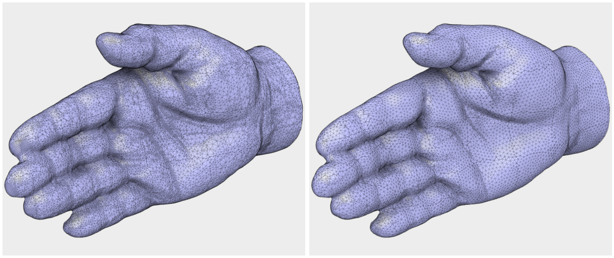
The Remesh tool re-meshes the model so that it has a more evenly distributed number of triangles. You can play around with density of the triangles, maintain sharp edges and boundary geometry so your model doesn’t get all wonky. Get a preview of what the mesh is going to look like by checking the Preview checkbox before you commit the action. Below is another example of an original mesh files (left) vs. a remeshed version at 40% density (right).
If the model still has too many triangles, you can reduce the amount with the Reduce tool. Much like how the Remesh tool behaves, select the entire body in the browser or paint over the area you’d like to reduce. Then change the density and get a preview for how it affects your model.

So what if you wanted to remove entire features of a mesh model? Or maybe you want to plug up a hole in a 3D scan? No problem, you can do that with Erase and Fill. Select the area of you want to go away and poof, it’ll magically disappear with that area automatically cleaned up.

– Rebuilding a Mesh Body
If the mesh model you are trying to modify is either out of whack and needs a more drastic overhaul, or just have a bunch of openings that you want plug up and turn the model into a closed mesh, then Rebuild as Solid is the tool for you. This will rebuild the model by remeshing and closing any gaps the tool finds, making your model a solid mesh.

– Merging Mesh Bodies
If you have multiple mesh bodies you’d like to merge into one, we have a Merge tool that does just that. Similar to the Combine tool in modeling, you can decide to keep or discard the tool body. Once merged, your original bodies will be given their own color, signifying their own face groups for easier selection.

– Creating Sketches from Mesh Sections
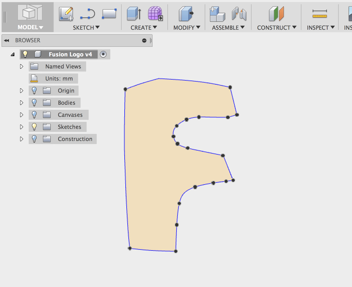
Another useful workflow is to create sketch geometry based on sections of your mesh body. Think of it as a way to reverse engineer a part you downloaded, or a 3D scan you obtained into a solid (BREP) model. Under the Sketch drop-down menu, we’ve added 2 new tools. Select Create Mesh Section and then click on the mesh body you’d like to use as reference. Then use the manipulators to get the section you want as a sketch profile, and then click OK to finish. Now you’ll see that a new sketch has been created with the section profile in it, ready for you to edit.
Now that you have a sketch profile to work with, this is where some manual work comes in. Right below the Create Mesh Section tool is the Fit Curves to Mesh Section tool. Within the sketch, use it to outline the profile with the necessary sketch curves. If you want the best results, we recommend using a combination of Line, Arc, and Spline Fit Curve Types to outline your sketch section. The Spline Fit Curve Type works pretty well.

Yeeahh…that’s pretty.
You can also try using Closed Spline Type, but be aware that the results generated by Closed Spline may not be as accurate as doing it manually. Notice that in this example, it didn’t do a good job at some of these sharp transitions. In this case, you’ll need to use the other Fit Curve Types such as Line, Arc, and Spline to trace the sketch properly. Keep in mind: a good model always takes time.

– Useful Tips and Fun Tricks
Before you go off exploring, here are a few helpful tips and tricks we thought you should know – we promise it’ll make the experience a whole lot better:
Double clicking on a face group will highlight the entire face group.

Pressing the square bracket keys “[“ and “]” will grow and shrink (respectively) your selection area. What a time saver!

Hovering over a hole/opening and then double clicking will highlight the hole perimeter. Because why not?

And here’s something neat: changing the Rebuild Mode to Blocky within the Rebuild as Solid tool will allow you create low-poly mesh versions of your design. Minecraft anyone?

Keep in mind that this is still preview functionality, and various experiences may be ultimately different when it graduates from a preview to production functionality. This is a good thing, because you can affect its direction by giving us feedback in the comments below or on the Forum. We’re excited to see what you will do with it. There are still a number of things we’re working on to improve this environment, such as quadrification of mesh triangles, turning them into squares/rectangles, which will essentially enable you to convert mesh models to T-Spline bodies. That’s right, you heard it. It’s gonna happen, and it’s just a matter of time.
Okay – let’s take a look at some of the other improvements and fixes we made in this update:
New Sketch Scale tool
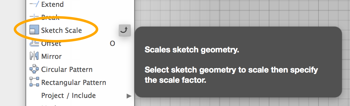
Now when you are working on a sketch within the sketch environment, you can use the Sketch Scale command under the Sketch drop-down menu to, you guessed it – scale your sketches. When you invoke the Sketch Scale command, a dialog box will appear, give you 2 selection options: the entities you want to scale, and the point from where you want to scale. Here are a couple things to note:
- If the point you want to scale from is on the sketch itself, it’s best to select the point first, and then select the entities. The same is good if you want to use the origin point yet you have sketches going through the the origin.
- If the point you want to scale from is outside the sketch entities, you can begin by selecting the entities and then selecting the scale point without any issues.
Sometimes when you had a broken sketch constraint, it would cause the feature to be highlighted as yellow in the timeline, letting you know that it’s sick and needs attention. Typically, deleting that constraint should have fixed the issue; however, we noticed a bug where the feature remained sick even after the broken constraint was deleted. Our developers gave Fusion some highly effective vaccines and now it’s all healthy again.
Once you’ve selected both the entities and the point, you can use the arrow manipulator and drag it left or right to get the scale factor you want, or set it numerically in the dialog box.
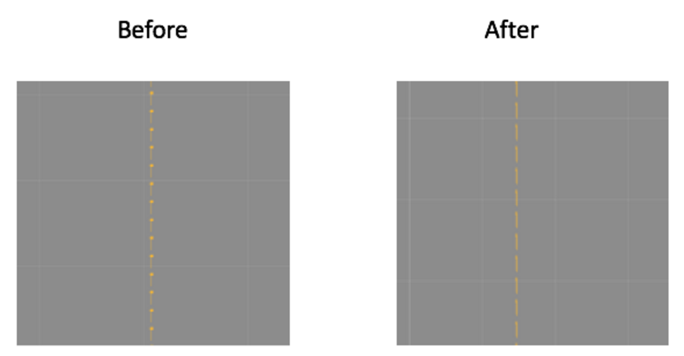
When creating construction lines in a sketch, the appearance of the construction line got a little wonky on MAC OS 10.10 Yosemite. They’re actually supposed to be clean dashes, so we made sure of that.
Here’s a great example how everyone is helping to make Fusion better. Some FIRST Robotics students reported that if a circle was sketched on an offset rectangle, the rectangle would automatically be converted into construction geometry. Great catch FRC students! Because of you, the bug has been fixed!
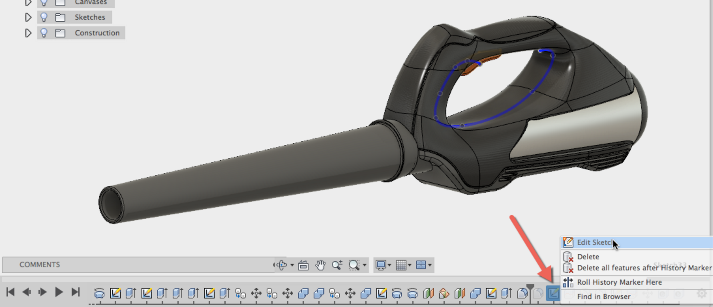
Previously, Fusion allowed the editing of sketches that were rolled back over. We saw how this could be dangerous to edit sketches that were technically suppressed, so now you can not edit sketches unless the rollback bar is to the right of the sketch.
HughesTooling reported a bug that made Fusion crash when he tried to see properties of an imported design. We examined his sample file and found some wonkiness – no worries though, we got it all sorted out now.
While everyone is trying to catch rare Pokemons, we’re all about catching rare Fusion bugs. We fixed a long standing issue in the Sculpt environment where if you were in Edit Form and were editing a T-Spline body, cancelled out of the command, undo’d a couple of times and then did a redo, Fusion would no longer let you select the T-Spline body. We’ve been having a hard time trying to reproduce this issue, until recently, one of our rad developer Lei Zhang in Shanghai, China finally found correct workflow to see the issue pop up. What a relief!
Usability
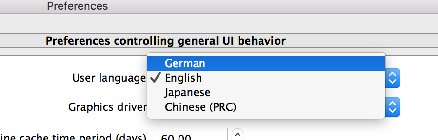
Fusion 360 is now in German – Fusion 360 auf Deutsch? Ich glaube ich spinne. Nein, das ist echt. herzlich willkommen!
This also means you’ll be able to access A360 in German as well. This has been in the works for quite some time, but supporting a new language isn’t as simple as flipping a switch and turning everything into that language. A lot of design work was done to make sure that visual requirements are met, that everything works as it should, and that there is local language support for our German users. As we continue to expand coverage, stay tuned for updates to the Fusion 360 mobile app, as well as our learning content. In the meantime, be sure to visit the German Fusion 360 forum!
To change the language, simply go to your preferences and change the language to German.
Deep Update is here – Now when you make a change to a component that lives within another component, you no longer have to manually update up the chain so that the entire assembly is up-to-date. All you have to do now is update once and Fusion will update the rest for you.
The Space Mouse. The Final Frontier of mouse exploration. Well, not really, but who doesn’t love flying around their models with a nubby top-hat shaped device. You’ll be glad to hear that the Space Mouse orbit center now uses consistent logic with mouse/trackpad by orbiting around the center of the bounding box. In addition, when a portion of the model is off the screen, the orbit point resets to the center of the screen after each move. Below is a quick demo of the previous behavior (left) vs. the current behavior (right).
Body names now become component names when converted – This is one of those make-your-life-so-much-easier kind of improvements (requested here, here, and here). Now when you convert a body into a component, the body name (if you’ve renamed it) will automatically carry over to the component name. No longer do you have to manually rename every component while muttering profanity at your computer screen.
Inventor file format now updated to 2016 – Now when you share a design with someone else or when you access your design via A360, you’ll be able to export the design as Inventor 2016 file format, instead of the old Inventor 2014 version. It’s about time we updated this. Moving on.
Here are some other notable usability improvements:
- Speaking of exporting, EricSchimel reported an issue where exporting a Fusion design as a SketchUp file resulted in his patterned subassemblies not showing up correctly. We dug into this and found that there was an issue with how SketchUp and Fusion 360 spoke to each other regarding the assembly hierarchy. Apparently things got lost in translation (figuratively and literally). Now they understand each other perfectly fine.
- For some reason when trying to sort through designs in the data panel, nothing would change the first time when the sort type was changed. You would have to select it twice to make it work. We fixed that issue so it works the first time…as expected.
- Before if you had a mis-matching time zones while using Fusion 360, our error messages didn’t give you much information. Now we improved the error message to give you decent information for next steps to resolve the issue.
Graphics and Visualization
We’ve upgrade our graphics engine that improves performance of shaded and wireframe visual styles that include hidden edges. Things should run smoother now.
KirillChepizhko shared with us an issue where using the arrow manipulators to move an attached canvas image did not behave correctly. This thread further revealed some issues related to decals as well, where they would show up as black rectangles. Both issues are now fixed.
Harvid22 reported a problem with the rectangle pattern where the pattern constraint icon could not be selected, which in-turn prevented the pattern to be updated. Zooming into the pattern also made the icon disappear for some reason. We’ve tightened this up and now it works as it should.
We found a regression issue where if you moved a body, captured it’s position, then proceeded to do a draft on a face, the selected face you wanted to draft against remained highlighted at it’s original location, as if there was a ghost body. Our Fusion ghostbusters did a quick sweep of the place and Fusion is now ghost free.
2D Drawings
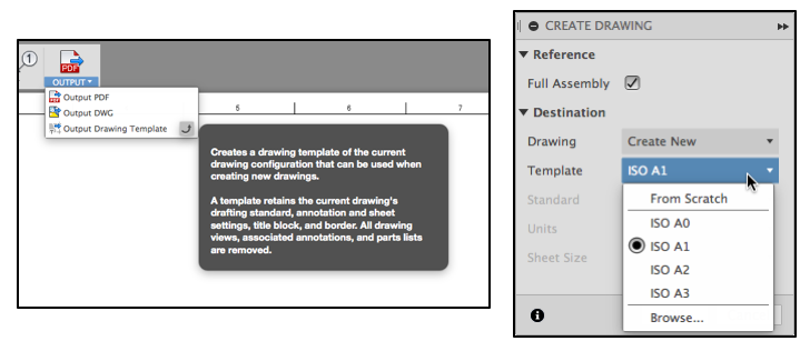
Templates – Remember when we had to change the settings for every new drawing? Not anymore. Now we can create templates, which will store annotation settings, sheet settings, title block logos, and text that will go on every page (i.e. confidentiality notices). BAM!! Go set up your various drawing settings, output a drawing template, and use it on your next drawing.
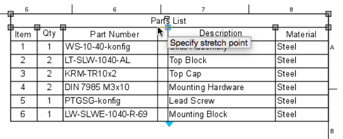
Part List Enhancements – In a large assembly, some part’s lists are so long they are run off the page. This was an issue. Now we can split the parts list by grabbing the blue grip handle. In addition, we can change the width of the columns by grabbing the grey grip handles to customize the size of the parts list.
UI Improvements – Sometimes when you switch to make a drawing it felt like we were jumping to a different world. We have done a lot of work to have the drawings UI work and match the rest of the Fusion 360 UI.

We’ve gotten reports around how an exploded view created in the Animation workspace wasn’t displaying as an exploded view when you added it to a 2D drawing. Kinda defeats the purpose of having multi-asset support, doesn’t it? Our bad – this is now fixed.
We noticed a regression issue where if you wanted to create a new drawing from your design, and did this by right clicking the design in the data panel, then selecting “New Drawing from Design”, Fusion 360 would crash. Now it doesn’t anymore.
HSM
For reasons beyond our comprehension, if you used the “Metal” material while simulating your tool-paths, Fusion had none of it, dropped everything and threw a fit. We were able to teach it to embrace metal, and now it loves it.
Now when you go back to your library tree view in CAM, Fusion will remember whether you had the tree view open or closed. Neat!